Setting up ESP8266 NodeMCU with MicroPython
This is different… hardware hacking?
I’m sort of between side projects at the moment, and as I was closing some browser tabs from the previous project, I noticed a new link on Miguel Grinberg’s site for a MicroPython/IoT course he’s making. I’ve wanted to dig into this sort of thing for a while, but always assumed the time investment would be too high relative to what I have available. After reading the first couple of installments of his course, I learned two things:
- The hardware looks very cheap, so it’s easy to mess around without a serious commitment.
- I can still use Python, the language with which I’m already most familiar, so it should be easy to come up to speed.
What I want to build
Another reason I’d not delved into this sort of thing before is I usually don’t have a good project in mind. I do enjoy learning new things just for the sake of learning, but I’m much more motivated to stick with something if I have a tangible end goal in mind from the start. In this case, there was something I’ve been mulling over already that seemed like a great fit.
A few months ago, our old mercury-type thermostat stopped working, and I replaced it with the cheapest, dumbest thermostat I found at Home Depot. I had been eyeing some of the smart thermostats they had, but couldn’t justify the price tag and really didn’t need many of the features compared to the cheap bimetallic one I actually bought. But I’m still a nerd, so I kept thinking about being able to control the thermostat from anywhere in the house (or while away on vacation), and have it automatically adjust based on time of day or whatever else I chose.
Seeing the parts list that Miguel listed immediately brought this idea back to mind. The project he goes through in his series is just a temperature/humidity monitor that logs data to visualize on a web page, but in my mind that’s just a few steps away from building a thermostat to replace this:
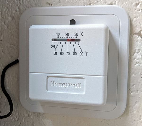
My boring thermostat that I want to replace
Choosing a development board
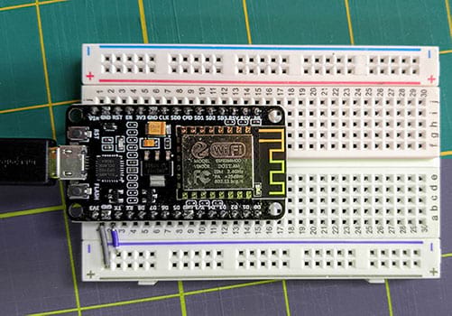
I honestly didn’t put a lot of effort into researching what board to start with, and just went with what Miguel was already using. The NodeMCU ESP8266 seemed pretty popular, has MicroPython support, and was super cheap (about $19 for four of them). It supports a reasonable number of GPIO pins (although only a single analog pin), and has onboard WiFi.
It looks like it’ll do just about everything I need for this project, and I didn’t want to go down the rabbit hole of trying to find the “best” board instead of moving forward with something that’s good enough. I also ordered a few breadboards with jumpers, and a micro-USB cable to provide power and data connection to the board.
Links to Amazon (affiliate links, so I might get a couple of cents if you use them):
- NodeMCU ESP8266
- I bought a pack of four, but they can probably be found for cheaper if you just want one.
- Breadboards & jumpers
- There were a lot of extra jumpers in here I’ll likely never use. There may be something better suited, but I just wanted to get started.
- Extra jumpers
- These are totally optional, but I wanted more length options than what came with the breadboard.
- Micro-USB cable
- I probably have way too many of these hiding around somewhere, but I can never find them when I need them.
There’s more parts I’ll end up needing, but that’s enough to get started and make sure this is really the direction I want to take.
Basic hardware setup
First thing is to get power to the board, which is easy via the micro-USB port. Since I’ll need the same port to flash and then program the board, I just plugged it into an available USB port on my computer for now. Eventually I’ll dig up an unused USB power adapter so I can plug it into the wall at its final location.
The breadboard I bought is just barely wide enough for this MCU (likely by design), so there’s one hole free on either side when it’s plugged in. If you’ve not done this sort of thing before, just press down carefully but firmly on both sides and insert it fully into the breadboard. You shouldn’t be able to see any of the metal pins when it’s correctly seated.
I know I’ll need to power some peripherals as well, so I also connected 3.3V and ground from the MCU to the power rails on the breadboard. There’s a few options for the 3.3V (labeled as 3V3) and GND pins, but I arbitrarily chose the two you see in the photo below. For this project I’ll probably stick to the USB jack as a power supply, but it’s worth noting that the MCU can also accept power through these pins instead of supplying, if you already have an external voltage source.
USB, 3V and ground connected
Firmware flashing
The MicroPython documentation has a good section on getting started with the ESP8266 that I followed closely.
The first thing needed is USB-to-UART driver to be able to talk to the MCU over the USB connection. There are drivers for Windows and macOS here. I’ve read that additional drivers are not needed for most Linux distros, but haven’t confirmed that.
Next, I downloaded the MicroPython firmware .bin file from here. I used the latest version at the time, which was v1.11. Make sure you get the .bin file, and not download the full MicroPython source, which is only needed if you want to extend the code, or to freeze your own program and install it as a binary. In my case, I don’t need to do either.
Esptool is a utility maintained by Espressif (the company that makes the ESP8266 chipset) used to flash the firmware on this chip. I installed it using pip install esptool. Note that this assumes you already have Python and pip installed on your computer, but if you don’t and aren’t sure how to do that, there is plenty of information available on the internet regarding how to install Python for your given operating system.
I wanted to erase the flash memory before writing the MicroPython firmware, but to check everything was communicating correctly first, I ran esptool.py read_mac to make sure it could talk to the board over the serial connection. The output looked like this:
$ esptool.py read_mac
esptool.py v2.6
Found 2 serial ports
Serial port /dev/cu.SLAB_USBtoUART
Connecting........_
Detecting chip type... ESP8266
Chip is ESP8266EX
Features: WiFi
MAC: a4:cf:12:bc:37:88
Uploading stub...
Running stub...
Stub running...
MAC: a4:cf:12:bc:37:88
Hard resetting via RTS pin...
I noted the serial port to use in the next few commands, in this case /dev/cu.SLAB_USBtoUART
Before uploading the new firmware, I erased whatever was already on there using the command below. If you had a different port from the read_mac command, use that one instead.
$ esptool.py --port /dev/cu.SLAB_USBtoUART erase_flash
esptool.py v2.6
Serial port /dev/cu.SLAB_USBtoUART
Connecting........_
Detecting chip type... ESP8266
Chip is ESP8266EX
Features: WiFi
MAC: a4:cf:12:bc:37:88
Uploading stub...
Running stub...
Stub running...
Erasing flash (this may take a while)...
Chip erase completed successfully in 1.7s
Hard resetting via RTS pin...
Finally, I could write the MicroPython firmware. If the filename if the version you downloaded is different than mine (esp8266-20190529-v1.11.bin), use that filename instead. If you have trouble getting this step to work, the MicroPython documentation I linked above has some suggestions for changing baud rate, but I didn’t have any problems. It took a minute or so to flash, but kept updating progress so I didn’t worry it had frozen.
$ esptool.py --port /dev/cu.SLAB_USBtoUART write_flash 0 esp8266-20190529-v1.11.bin
esptool.py v2.6
Serial port /dev/cu.SLAB_USBtoUART
Connecting........_
Detecting chip type... ESP8266
Chip is ESP8266EX
Features: WiFi
MAC: a4:cf:12:bc:37:88
Uploading stub...
Running stub...
Stub running...
Configuring flash size...
Auto-detected Flash size: 4MB
Flash params set to 0x0040
Compressed 617880 bytes to 402086...
Wrote 617880 bytes (402086 compressed) at 0x00000000 in 35.5 seconds (effective 139.2 kbit/s)...
Hash of data verified.

Leaving...
Hard resetting via RTS pin...
Making sure it all worked
The real test of all the above steps is to try to connect to the MCU and access a Python REPL. This can be done with the screen utility that comes with Linux and macOS, but I found it to be a pain to use. There are several other possible options, and I chose to use rshell, which is specifically designed to work well with MicroPython. In addition to giving me a REPL, it also gives me filesystem info so I can copy my programs to the MCU when I’m ready. I installed it using pip install rshell, then tested the connection:
$ rshell --port /dev/cu.SLAB_USBtoUART
Using buffer-size of 32
Connecting to /dev/cu.SLAB_USBtoUART (buffer-size 32)...
Trying to connect to REPL  connected
Testing if ubinascii.unhexlify exists ... Y
Retrieving root directories ... /boot.py/
Setting time ... Jun 20, 2019 19:22:56
Evaluating board_name ... pyboard
Retrieving time epoch ... Jan 01, 2000
Welcome to rshell. Use Control-D (or the exit command) to exit rshell.
This dropped me into a TTY session on the board. Typing help will list available commands, which will be familiar to macOS/Linux terminal users. The filesystem setup seemed a bit strange at first, but basically it acts as if you’re still at the path you initiated rshell from, but with a root folder /pyboard that is the actual NodeMCU fiilesystem root. Here’s a quick example:
/Users/anson/src/hardware/thermostat/client/sensor> ls
config.py        main.py          sample_config.py
/Users/anson/src/hardware/thermostat/client/sensor> cp main.py /pyboard
/Users/anson/src/hardware/thermostat/client/sensor> ls /pyboard
boot.py main.py
The first ls command lists the files in the folder on my computer. The cp command copies the main.py file from my computer to the MCU. The ls /pyboard command shows that main.py is now copied to the MCU filesystem. The other file, /pyboard/boot.py, comes as part of MicroPython, and I’ve just left it alone for now.
Other commands that might be useful are:
cat filenamewill print out the contents of the filecdchanges directoriesexitwhich (hopefully as expected) will drop you out of the rshell session and back to your computer.editwill use your computer’s preferred editor (obviously vim!) to edit a file, and then save it back to the board.mkdirmakes a directoryreplgives you a MicroPython interpreter shellrmremoves a file
Anyway, just to test I can move forward with programming this thing:
/Users/anson/src/hardware/thermostat/client> repl
Entering REPL. Use Control-X to exit.
>
MicroPython v1.11-8-g48dcbbe60 on 2019-05-29; ESP module with ESP8266
Type "help()" for more information.
>>>
>>> print('it worked!')
it worked!
>>>
Wrapping up
I’ll write more about this project, but a few more tips for now:
- From the REPL, Ctrl-X will exit the REPL back to the rshell prompt.
- From the REPL, Ctrl-D will soft-reboot the MCU.
- From the rshell prompt, either
exitor Ctrl-C will drop you back to your normal terminal.